Operation of vacuum stepper motors
Posted on Friday 2nd July 2021 at 9:00
Stepper motors are typically digitally controlled using a stepper motor drive and can’t be driven in the same manner as a conventional AC/DC universal motor. They are the main components in open-loop motion-control positioning systems as they are capable of achieving clearly defined rotational positions, speeds and torques making them ideally suited to tasks requiring highly accurate and precise movement control.
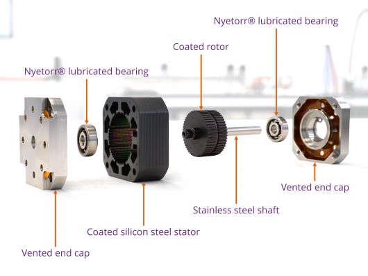
Our vacuum compatible stepper motors share the same basic operating principles as standard hybrid bipolar stepper motors, with several material and construction differences to reduce outgassing in a vacuum. The image below shows the components of our UHV compatible stepper motors:

Universal vs. stepper motor.
A conventional AC/DC universal motor has two power terminals that when connected to a power source cause the commutator to rotate. Reversing the polarity of the power source causes the direction of rotation to reverse.
Stepper motors are very different and require dedicated electronics to operate. This is because, a stepper motor consists of multiple phase windings coiled around the stator. The number of phases and the stepper motor type determines the number of electrical contacts that need connecting to the stepper motor drive. AML’s D-series stepper motors have 2 phases, resulting in 4 electrical phase leadouts (2 – 3 additional leadouts are present for thermocouple/RTD connections).
Stepper motor types
There are several types of stepper motor. AML stepper motors are hybrid stepper motors, but it is advantageous to be familiar with permanent magnet and variable-reluctance stepper motors, in order to understand the operating principle of hybrid stepper motors.
Permanent magnet
A permanent magnet motor includes a permanently magnetised, toothless, rotor that aligns with the magnetic field produced by the energised stator coils. The rotor has alternating north and south poles parallel to the rotor shaft. The pros and cons of a permanent magnet stepper motor are:
| Pros | Cons |
|---|---|
| Low cost | Low resolution, typically 7.5° - 15° per step (48 – 24 steps per revolution) |
| High torque | Limited acceleration and maximum speed |
| Simple construction | Low torque to inertia ratio |
Variable-reluctance
A variable reluctance stepper motor has an unmagnetized, ferrous, toothed rotor, where the teeth are attracted to the energised stator coil of least reluctance. The attraction causes the rotor to rotate so that the teeth are centred around the active magnetic field. Some pros and cons of variable-reluctance stepper motors are:
| Pros | Cons |
|---|---|
| High torque to inertia ratio | No detent torque |
| No permanent magnet | Typically 3.6° to 30° step resolution |
| High acceleration and maximum speed | High torque ripple |
Hybrid stepper motors (as used by AML)
AML use the hybrid stepper motor design for their UHV-compatible stepper motors. Hybrid stepper motors are a combination of the permanent magnet and variable-reluctance motors. Here is a brief overview of the pros and cons:
| Pros | Cons |
|---|---|
| High torque | High inertia |
| Provides detent torque | Higher cost |
| Small step angle (typically 1.8°) | Greater mass |
They are manufactured with 4 coils per phase wound around a 40 tooth stator and an axially aligned 50 tooth rotor. The rotor has two halves where the teeth on each half are offset from each other by half of the pole pitch. Knowing the number of teeth on the stator and rotor (40 and 50 respectively), the step angle can be determined, as shown below:
\[Step\ angle=\frac{\left ( 50 - 40\right )\times360^\circ}{ 50 \times 40}=1.8^\circ\]
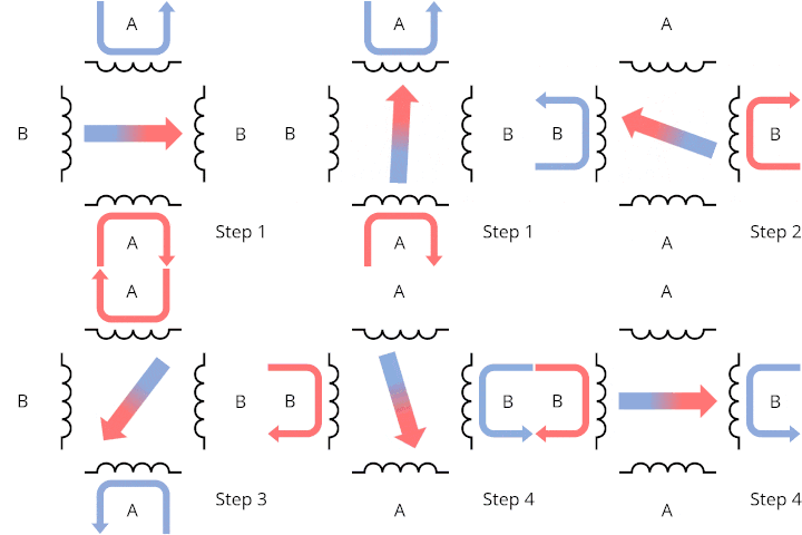
Although our stepper motors have a total of 200 steps per revolution, to help visualise how rotation is induced, consider a stepper motor with only 4 steps. The phases are coiled around the stator in alternate directions; meaning that magnetic fields of opposite polarities are generated when the phases are energised.

The magnetic fields present when phase A is energised in the positive direction causes the magnetic poles of the rotor to attract in the corresponding orientation. Then energising just phase B in the positive direction will cause the rotor to rotate 90°. A full 360° rotation can be completed by reversing the polarity of both phases as shown in steps 3 and 4. This method of operation is the simplest to understand and is referred to as wave-drive stepping. Other drive techniques will be expanded upon in a future blog post. These include:
- Full-stepping
- Half-stepping
- Quarter-stepping
- Micro-stepping
Unipolar vs. bipolar
Unlike a unipolar stepper motor, there is no centre tap in a bipolar stepper motor, so the polarity of each phase needs to be reversed as the rotor rotates. A benefit of passing current through the entirety of the phases (as opposed to only half in a unipolar motor) is that the torque output is much greater. In situations where torque output per mm3 is crucial, for example in a vacuum chamber, optimising the space utilisation is critical.
Operating in UHV
For optimal UHV operation, there are several material and electrical aspects to consider for minimising outgassing.
Wherever possible applications should be designed so that the load may be held in a position by the detent torque of the motor, so that power may be removed between periods of motion; to minimise temperature rise and outgassing.
Since the motor must be continually powered to maintain a micro-step position, micro-stepping is not a suitable method of increasing resolution for UHV applications. Angular resolution may be improved by reduction gearing.
Our ultra-high vacuum compatible bipolar stepper motors are manufactured in the UK, in our ISO Class 7 cleanroom. Certain materials and manufacturing techniques are used to provide the highest UHV compatibility.
- Vented end caps – designed to eliminate virtual leaks caused by trapped volumes
- Open bearings – lubricated with Nyetorr® ultra-low outgassing grease (dry MoS2 option available)
- Silicon steel stator – coated with UHV-compatible coating
- Rare earth magnet rotor – coated with UHV-compatible coating
- Stainless steel shaft (modifications available upon request)
Refer to our “How an AML UHV-compatible stepper motor is made” blog post for more information on the manufacturing process.
As with all of AML’s products, our UHV compatible stepper motors undergo a stringent quality assurance process, ensuring that they meet AML’s high standards.
AML offers a range of products specifically designed to work with our high-quality ultra-high vacuum compatible stepper motors, including our stepper motor drive, and our UHV mechanisms.
For more information about our range of stepper motors, please do not hesitate to contact our dedicated team by emailing info@arunmicro.com.


