Ion gauge history
AML’s nude ionization gauges are designed on the principals explored by Robert T. Bayard and Daniel Alpert in the 1950s. Commonly known as the BAG, or BA gauge, the Bayard-Alpert gauge is an evolution of the triode gauge developed in the early 1900s. The triode gauge used a cylinder as an ion collector. It was capable of measuring down to 10-8 Torr, with the lower pressure limited as a result of soft X-rays generating a photocurrent that added to and was indistinguishable from the actual measurement. This point is called the X-ray limit.
Bayard and Alpert reduced the ion collector from a large cylinder to a fine wire, decreasing the size of the photocurrent in relation to the measurement. This considerably extended the lower end of the pressure measurement range, advancing the state of the UHV (ultra-high vacuum) measurement field. AML utilise a thin but rigid wire, ensuring mechanical stability and achieving an X-ray limit of 3x10-11 mBar.
Operating principle
The ion gauge works by ionising the gas molecules within the gauge volume. The ions are then collected on a thin wire, called the collector. The current formed is proportional to pressure. BA gauges are capable of measuring pressures in the range of around 3x10-11 mBar to 1x10⁻³ mBar.
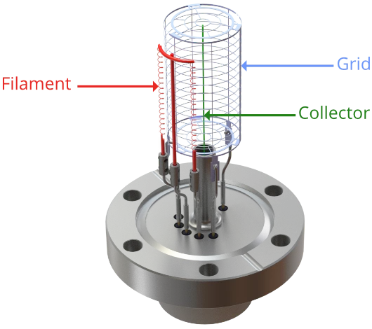
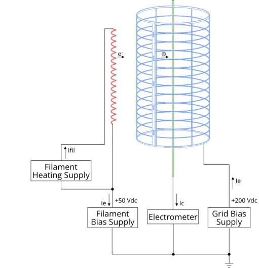
In addition to the collector mentioned above, the ion gauge comprises a grid and a filament. The filament is heated with a low voltage, high current supply, and biased at around 50 V. Electrons boil off of it and are accelerated towards the grid due to the potential difference between the two.
The grid is held at a potential of about 200 V, and a current of energetic 150 eV electrons orbit the grid. This current is called the emission current. Emission current is closely regulated by the ion gauge controller by adjusting filament power. It is typically in the order of 0.1 mA to 10 mA.
These electrons encounter gas molecules as they circulate, ionising them. These ions are attracted toward the negatively biased collector (held at 0 V) and form a small current (typically between a few picoamps and hundreds of microamps). This current is proportional to pressure, according to
Where Ic is the collector current in amps, is sensitivity and is the emission current. The ion gauge controller measures the collector current using an electrometer (essentially a very sensitive ammeter) and converts it to a pressure measurement for display.
It is desirable to reduce the emission current because this minimises outgassing and power dissipated by the gauge. Reducing emission current results in a smaller ion current to measure, requiring a sensitive electrometer. AMLs ion gauge controllers are designed to operate at an emission current of just 0.5 mA, only needing to increase to 5 mA at the lowest pressures. This is made possible by a highly sensitive electrometer design.
Filaments are usually tungsten or coated Iridium; the latter is more efficient and can survive exposure to much higher pressures without damage. AML offer tungsten, yttria coated and thoria coated iridium filaments. Gauges are equipped with two filaments for redundancy; should a filament fail, the alternate filament can be used, without requiring downtime in the chamber to replace the filament.
All of our Bayard-Alpert ion gauges are manufactured in the United Kingdom, in our ISO Class 7 cleanroom, and undergo a stringent quality assurance process, ensuring that they meet AML’s high standard of quality.
For more information about our range of vacuum measurement instrumentation, please do not hesitate to contact our dedicated team by emailing info@arunmicro.com.